Using a Nextion 5110
Display
with MMDVM
revised d. bodnar 12-17.2018
|
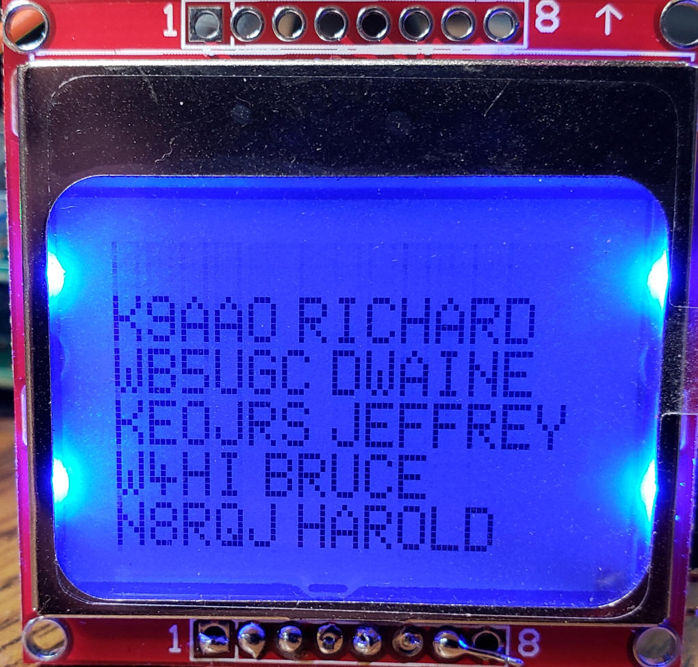
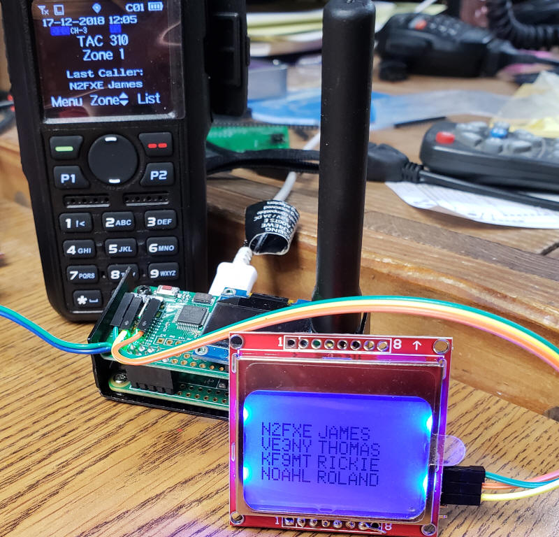
Introduction The MMDVM hot spot (also called the Jumbo Spot or the China Spot) comes with a small (0.9") OLED display. While this provides important information and can be used to see call signs and names it is so small that many cannot see the small text without strong lenses. The Nextion display takes care of this issue as it dramatically larger than the OLED display. I use the Nextion display in my home, car and while riding my bicycle. After using these displays for many, many hours I have found that the only really important things that I look for are a ham's call and first name. The Nextion provides this information but it only displays it for a short time. On a recent bike ride I started to think about what I would like to see on a display and decided that just a list of the latest caller's call & name along with a short list of the previous callers.
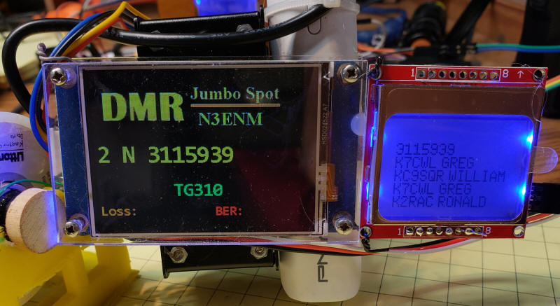
As an added bonus I found that the MMDVM hot spot had no difficulty driving both the Nextion and the Nokia displays simultaneously as shown here.
My notes on how this was built appear here. This is not meant to be a thorough tutorial on the display, Arduino and associated software. If you want to try this yourself you should have some understanding of programming an Arduino and soldering the Nokia display, the Arduino and the Jumbo Spot. |
|
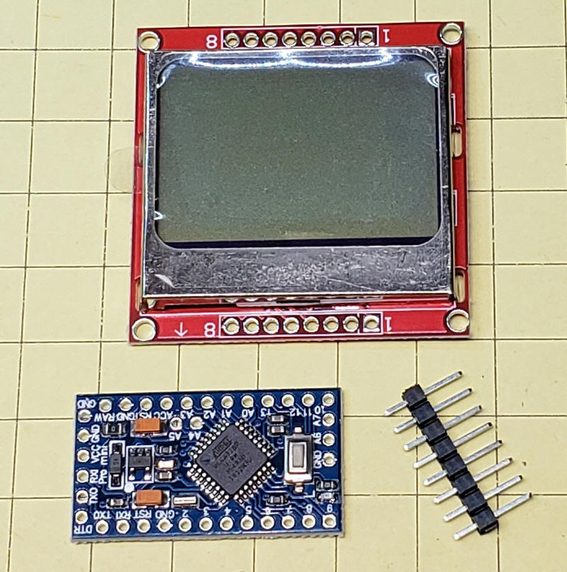
Hardware There are any number of displays that could have been used for this project. I decided to use an inexpensive and readily available display that was once used in Nokia call phones, the Nokia 5110 display. A great deal of information about this display is available on the Internet and they can be purchased on eBay for less than $5.00. For a bit more you can get them from Amazon. You may see that these displays are only for 3 volt operation. I have found that all of the units that I have purchased work just fine when connected to 5 volt devices. I needed a microcontroller to go between the hot spot and the display. Again, I opted for an inexpensive and well supported version of the Arduino called the Pro Mini. They are available from eBay and Amazon for a few dollars. Make sure you get the 5 volt version and, if you don't already have one, the serial programmer that allows you to program the Arduino.
PARTS
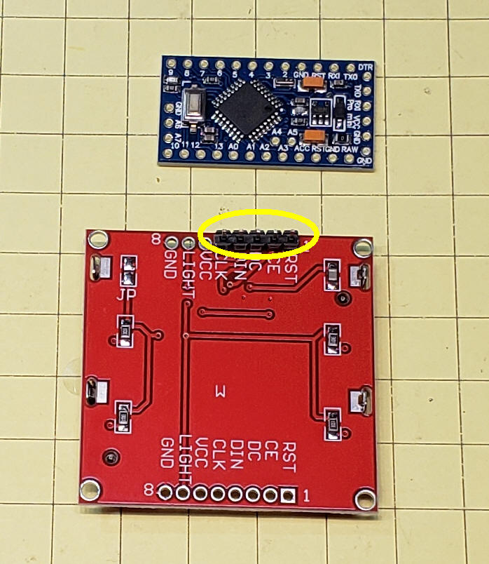
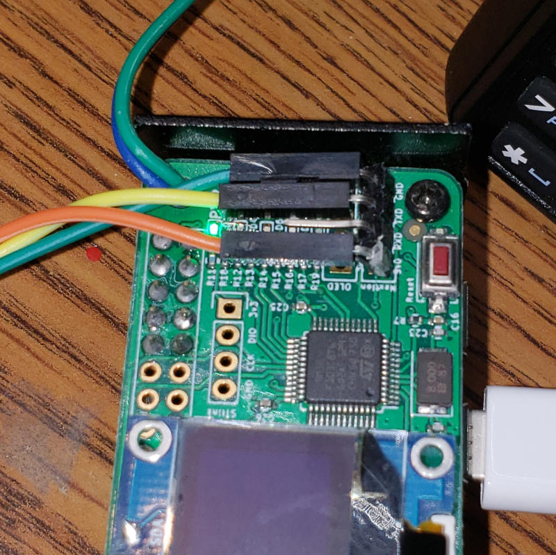
HEADER The pins circled below connect directly to pins 2 through 6 on the Arduino. Note that the three pins to the left (GND, LIGHT and VCC) are not connected with the header.
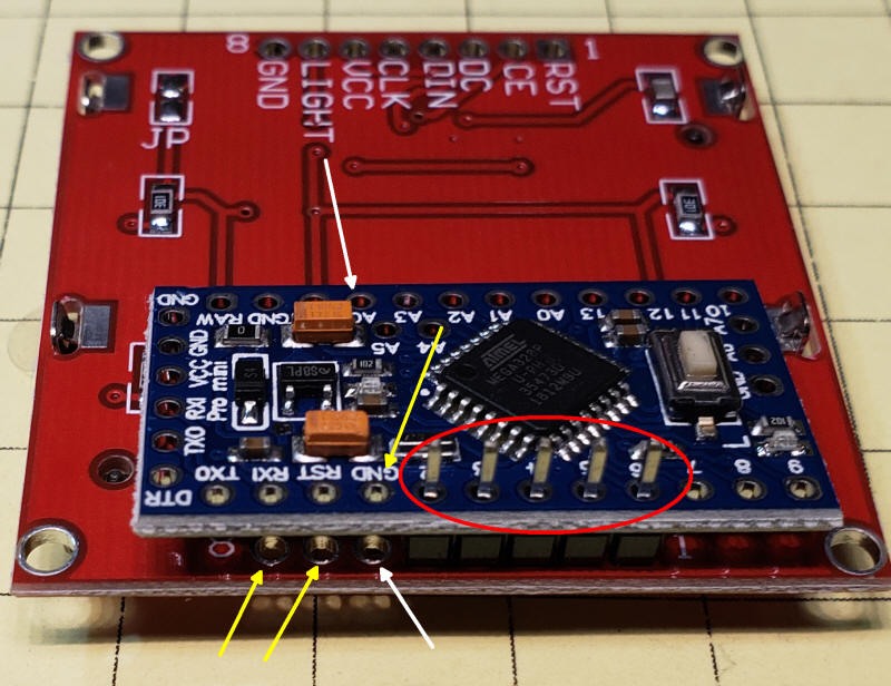
Solder the 5 pins (circled in red) to both the Arduino and the display. The three pins shown by the yellow arrows are connected and the two pins shown by the white arrows are also connected.
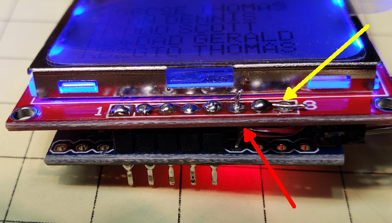
This photo shows the connections after soldering. The red wire (red arrow) goes under the board and connects to the Arduino's VCC (5 volt) pin. The two pins by the yellow arrow are joined together and then go to ground on the Arduino.
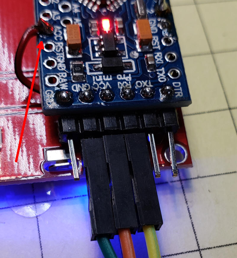
CONNECT TO JUMBO SPOT The connection to the Jumbo Spot are shown here. I soldered a 4 pin angled header to the top board and use that to connect to either the Nextion or to the Nokia display. Only 3 or the 4 wires are needed, VCC, GND and TXD.
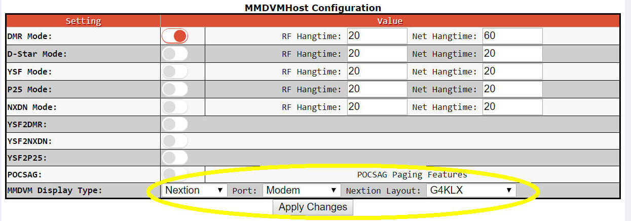
Pi-STAR Settings The settings that I used under Configuration on Pi-Star are shown here circled in yellow.
|
|
Software The software gets the serial stream that is normally used for the Nextion display from the Jumbo Spot. This stream of data is captured and parsed by the Arduino. It saves the last 5 callers and shows them on the display with the newest contact at the top. The code is shown here. It is not meant to represent good coding, it is meant to work! I am also sure that there are some bugs that may need to be dealt with. Please let me know if you make improvements. IMPORTANT NOTE - you may need to adjust the contrast value lcd.setContrast(55) (highlighted in the code below) as some displays need a bit more or less contrast. SerialBufferInput--withNokia--Working-v1-6-OK-changedPins // d. bodnar 12-17-2018
// working to pull name and call from Nextion serial stream from MMDVM unit
// some extra code is still there
#include "Nokia_5110.h"
#define RST 6
#define CE 5
#define DC 4
#define DIN 3
#define CLK 2
String array[] = {
" ",
" ",
" ",
" ",
" ",
" "
};
Nokia_5110 lcd = Nokia_5110(RST, CE, DC, DIN, CLK);
int found = 0;
int foundQuote = 0;
int firstTime = 0;
int divide = 0;
void setup() {
Serial.begin(9600);
Serial.println("Serial Test 1.6");
lcd.setContrast(55); // 60 is the default value set by the driver
lcd.clear();
lcd.print("Ready Display");
delay(2000);
lcd.clear();
}
char buf[200];
String wasCall;
unsigned int i = 0;
String callName;
void loop() {
Serial.setTimeout(10);
int len = Serial.readBytes(buf, 200);
String myString = String(buf);
found = myString.indexOf ( "2 N " );
foundQuote = myString.indexOf("\"", found + 5);
if (found >= 0 && found != 68 ) { ///68 ignores idle && wasCall != callName
callName = (myString.substring(found + 4, foundQuote));
if (wasCall != callName) {
array[0] = callName;
for (int xx = 5; xx >= 0; xx--) {
array[xx] = array[xx - 1];
}
for (int xx = 0; xx <= 5; xx++) {
Serial.print(xx);
Serial.print(" ");
Serial.println(array[xx]);
}
Serial.print("callName = ");
Serial.println(callName);
divide = callName.indexOf(" ");
for (int xx = 1; xx <= 5; xx++) { // starting @ 0 caused top line gibberish
lcd.setCursor(0, xx);
lcd.print(array[xx]);
lcd.print(" ");
}
}
if (firstTime == 0) firstTime = 1;
wasCall = callName;
}
}
|