
Robot Trains in the Garden
d. bodnar revised 4-18-2004
4:00 pm
Introduction
I have only been actively involved with garden railroading for a little over one year but have found it to be a wonderful way to use the skills and interests that I have developed over the years in other hobbies. For example, I used my love of woodworking to help me design and construct two scratch built bridges and nearly 100 trestle bents to support much of the 200 foot main line on the railway. My interests in photography, computers and web pages allowed me to document the work on the railway and share it with my friends and family, wherever they may live. (see: http://www.davebodnar.com/railway/ )
My latest collaboration between hobbies involves using my work with programming small, single board microprocessors and using them to control devices and sense things around them. For many years I have worked with small Basic Stamp microprocessors (see: http://www.parallax.com/ ). I have used the Basic Stamp to sense and react to temperature changes, monitor and control the charging of batteries, record the acceleration of model rockets and to operate small, autonomous robots. This project is a logical extension of my work with robotics as it involves using a similar microprocessor to control a battery operated railroad engine. The system is designed to have the engine slowly accelerate from a complete stop and then cruise at a preset speed until it passes over a magnet located on the track. When this happens a reed switch closes and the microprocessor gently slows the engine to a full stop. After a short pause the engine reverses and starts up again until it passes over another magnet when the process repeats.

Although the original objective of the system was the auto-reverse system as described above, the hardware is capable of much more sophisticated operation by modifying the software. It could, for example, have a train start off and pause any number of times at various locations identified by magnets in the track. In conjunction with another microprocessor and controller it could also cause turnouts to switch so that the train could follow a different route. The only limitation is one’s imagination. (In the event that your imagination is suffering from a long, cold winter I have some ideas at the end of this article!)
Having spent many years writing lesson plans for my classroom I always start off projects with a set of objectives.
Objectives
1)
The engine will be able to accelerate and decelerate smoothly, run
at a constant speed, stop and sense its location on the track
2) The engine will operate from batteries
3)
A microprocessor will control the train’s motion
4)
The microprocessor will must use interrupts to detect crossing
over a magnet so that no magnet crossings are missed
5) All motor control will be solid state using an “H-Bridge”
6)
Motor speed control will be by PWM (Pulse Width Modulation)
7) It will be possible to change some settings without reprogramming
8) Programs will be easy to create and revise
I have begun to switch much of my railway over to battery
power.
Microprocessor
Operation
Although most of the objectives for the project could be met by creating a circuit using discreet logic and timer integrated circuits the overall flexibility and design is simplified greatly by the use of a microprocessor. Changes can be made in seconds with a simple program modification rather than needing to rewire or add components to a circuit.
The choice of microprocessor is always a challenge.
The most popular small programmable system is the Basic Stamp by
Parallax. Unfortunately the two most
common “stamps” do not have interrupt capability.
The most inexpensive unit that supports interrupts costs nearly $80.00. A
new entry into the hobby microprocessor market is the PICAXE from
Interrupts
Interrupts are something that we use on our computer every day. Whenever we use a mouse on a PC we are using interrupts. An interrupt simply tells the microprocessor that something very important is happening and that it must “interrupt” everything else that it is doing so that it can deal with that special event. When you move your mouse it is very important that the PC not miss that movement. An interrupt is generated that stops other things, moves the mouse cursor and then returns to its other obligations. Our system has one very important event that can’t be missed. The microprocessor must catch every magnet crossing. The best way to insure this is with interrupts. Without interrupts, if the microprocessor is busy resetting the motor speed when a magnet is crossed it is possible that it would miss that event. Interrupts do a great job of making sure that does not happen.
Motor Control
There are several ways to control the direction and speed of an electric motor. A double pole / double throw switch (or relay) can be used to change the direction of rotation by switching the + and – terminals providing power to the motor. Speed can be adjusted by using switches or a rheostat to introduce different resistances into the circuit. The more the resistance, the slower the motor spins. Unfortunately the energy that the resistance takes from the motor is dissipated as heat, something that can be difficult to get rid of, to say nothing about being inefficient!
Solid state motor control can be accomplished with a number of different devices that simulate the operation of a double pole double throw switch. The easiest to use and interface to a microprocessor is called an “H-bridge’ due to its internal arrangement of transistors in an “H” pattern. A typical “H-bridge” has three control pins. Two of the pins determine the direction of rotation and the third is used for speed control. By applying the right sequence of controlling pulses to these pins the motor speed and direction can be set. Some heat still must be dealt with, but the overall system is much more efficient, something that is especially important when working with battery operated equipment
Pulse Width
Modulation
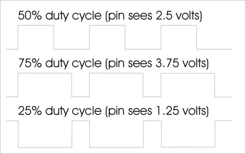
The objective that identifies PWM for speed control is part of the solid state motor control objective. When the microprocessor needs to change the speed of the motor it sends a series of pulses, called Pulse Width Modulation, to one of the “H-bridge” pins. This pin spins the motor at full speed if it sees 5 volts and stops the motor if it sees 0 volts. A voltage between 0 and 5 volts gives a speed proportional to the voltage. Microprocessors generally don’t deal well with variable, or analog, voltages. That is where PWM comes in. PWM sends a series of pulses of 5 volts to a pin to simulate a variable voltage. For example, if it sends pulses that are on ½ of the time the pin appears to have 2.5 volts on it. Sending pulses that are on 25% of the time looks like 1.25 volt and so on. (see graphic)
Changing Settings
with ADC
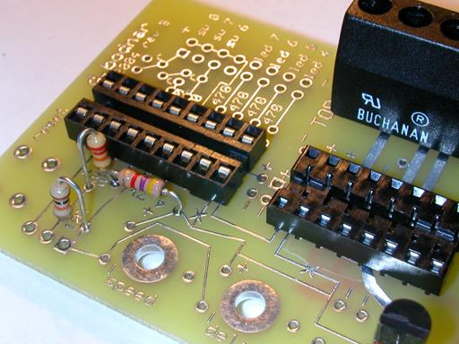
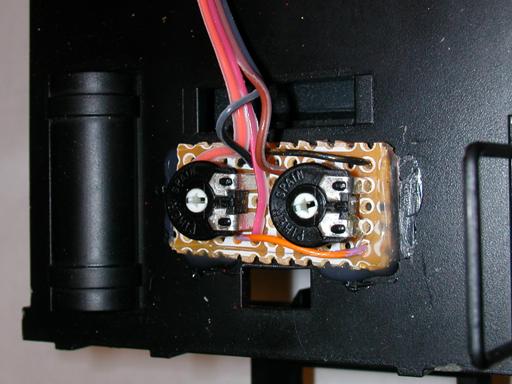
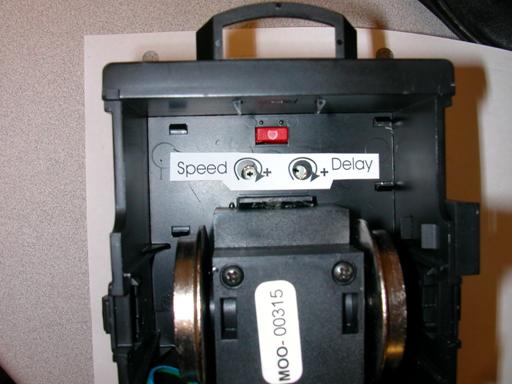
This project has a number of settings, or variables, that change the operation of the engine. Among them are the top speed setting, the rate of acceleration and the length of time to delay when the engine pauses between direction changes. While we could reprogram the microprocessor to change any or all of these settings that can be inconvenient when you are in the garden and don’t have a laptop handy! To make changes, several potentiometers (variable resistors, often called “pots”) have been included in the design. A potentiometer is a fixed resistor that has a movable wiper that can slide along the fixed resistor to provide a continuously variable resistance between zero ohms and the full value of the fixed resistor. Our microprocessor has the ability to do Analog to Digital Conversion (ADC). If we hook one end of the fixed resistor to 5 volts the other to ground and one of the input pins of the microprocessor to the wiper on the pot the microprocessor will see a variable voltage between 0 and 5 volts as the wiper moves across the fixed resistor. ADC converts this value to a number, usually between 0 and 255. Once we have that value we can use it to control speed, time delay and other settings. (see graphic of a section of the schematic showing one potentiometer connected to ground, +5 volts and pin 1 on the Picaxe)
![]()
BASIC Programming
The last objective may be the most important.
There are a number of microprocessors that meet the first set of
objectives but they use specialized and highly complex programming languages
that are not easy to learn and master. The
PICAXE family of microprocessors uses a version of the well known BASIC
programming language. BASIC uses
easily understandable commands and is a language that many people have already
experienced. The programming tools
to write, debug and send programs to the PICAXE are easy to use, run on nearly
any Windows PC and are a free download on the Internet.
Download it from http://www.rev-ed.co.uk/picaxe/
- click on Software and download the full program.
The Circuit
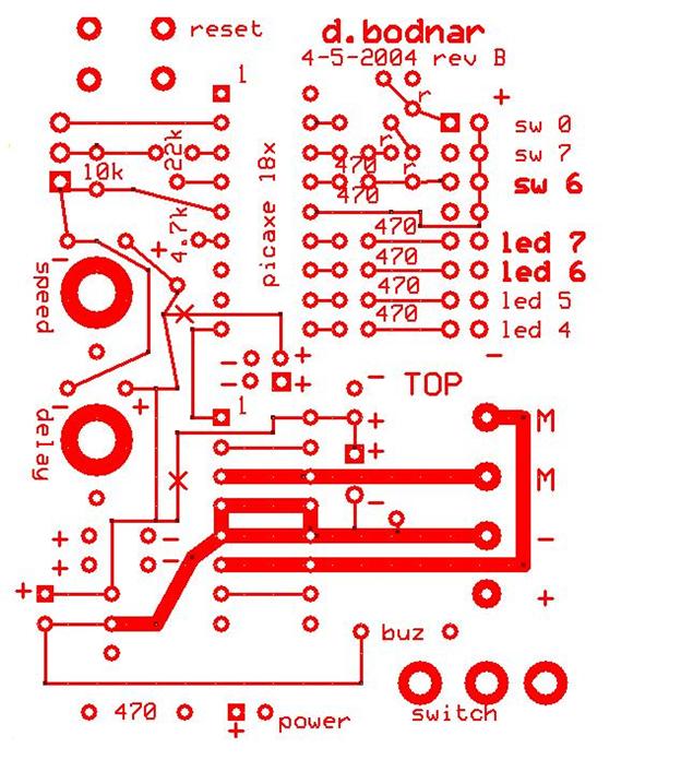
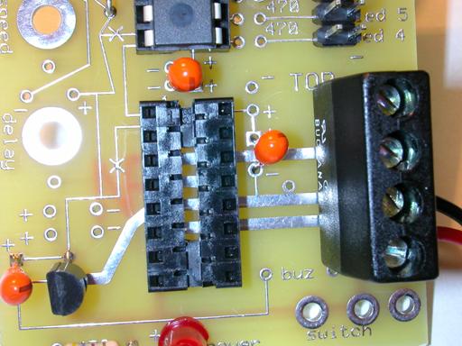
The schematic is a graphical diagram of each of the parts that make up this project. As you can see there are two ICs (Integrated Circuits), the Picaxe and the LM293D “H-bridge” and a number of other parts that tie the whole thing together. Spend some time familiarizing yourself with the schematic as it will be a great tool if you are in doubt about how to attach a part to the circuit board or if you are building the circuit on your own project board.
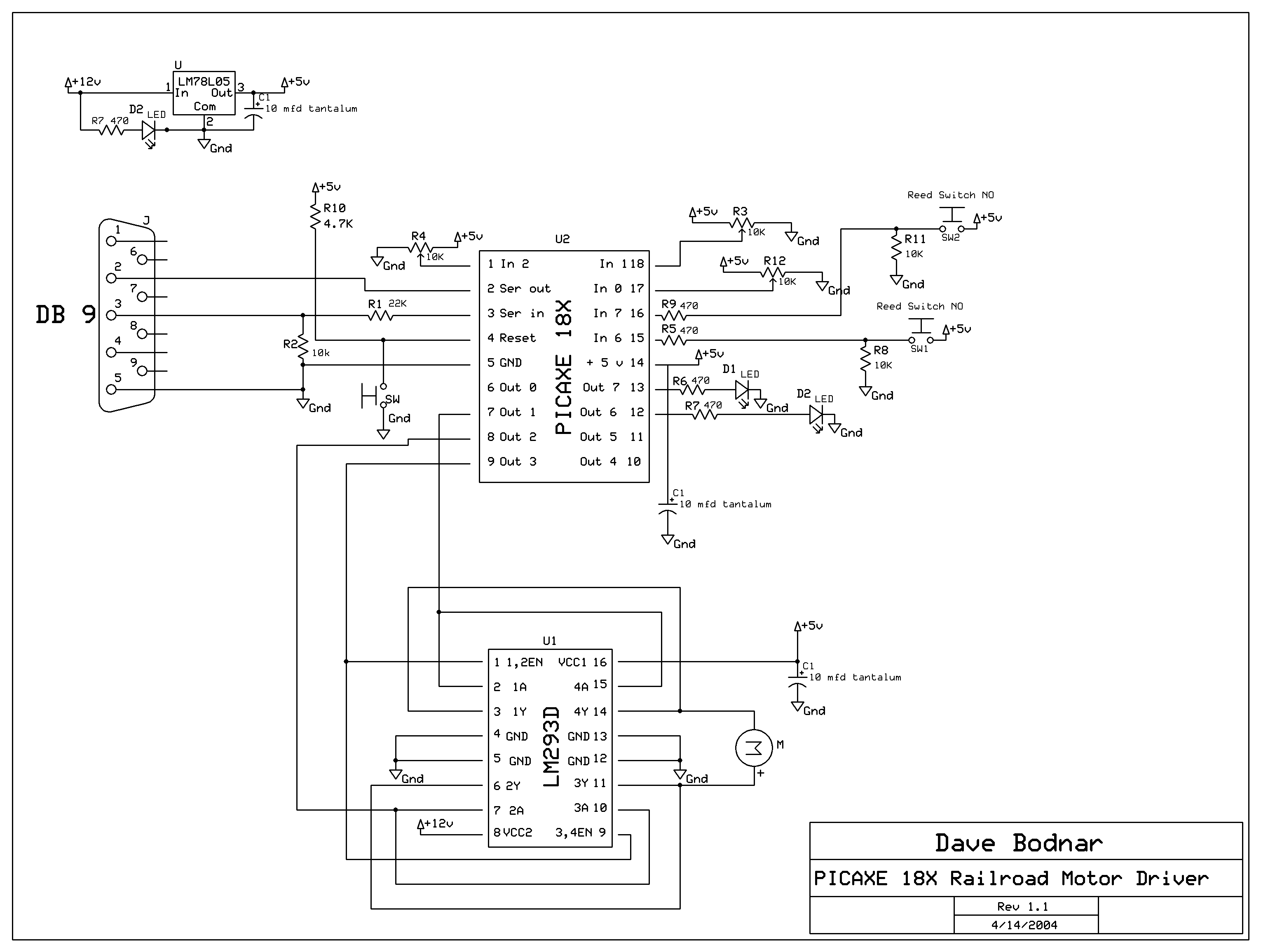
Parts list
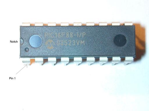
a. Microprocessor - PICAXE 18X
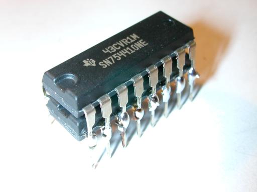
b. H-bridge - LM293D or sn754410ne
c. Voltage regulator - 78L05
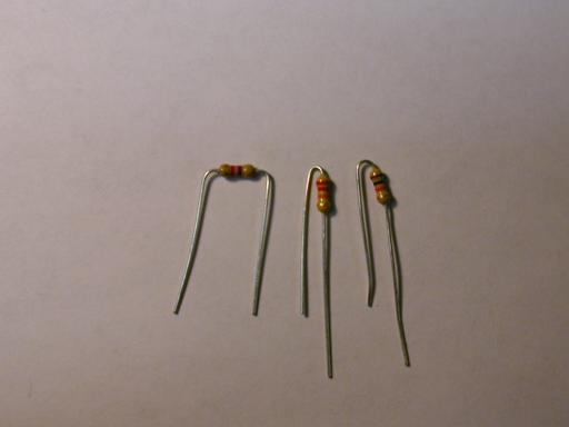
d. Resistors – 470 (7), 4.7K (1), 10K (3), 22K (1)
e. Potentiometers – 47K (2 or 3) – the value is not critical – anything from 10 K to 100 K should work
f. Capacitors – 10 mfd tantalum (3)
g. IC Sockets – 16 pin (1) and 18 pin (1)
h. LEDs – color is not important (3)
i. Switches – SPST (1) for power, SPST momentary (1) for reset
j. Reed Switch – small with normally open contacts (1)
k. Magnets – high strength (2 or more)
l. DB9 / Female connector (1)
m. Fuse or circuit breaker (1)
n. Circuit board (1) – prototype board or custom board
o. Wire, other connectors as needed for your installation
Parts
Tools
Prototype
Construction
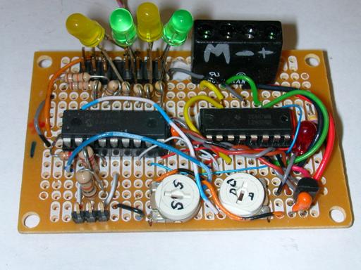
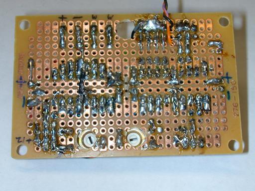
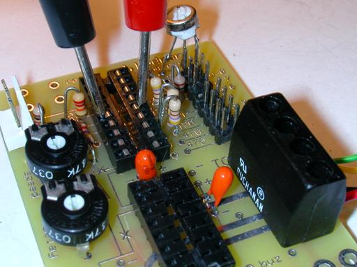
My first prototype for this project was hand wired on a Radio Shack circuit board (276-150). If you want to go that route the photos, parts list and schematic should be all you need. I built 4 circuits that way and found that each one took several hours to build and troubleshoot. Stripping and soldering tiny pieces of wire can be a bit of a challenge.
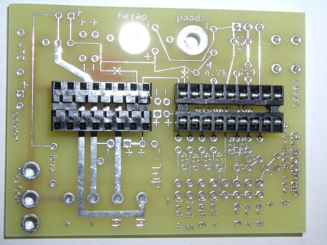
Custom Circuit Board
After getting the prototypes working well I came across a company that would make small batches of custom printed circuit boards. (see: http://www.expresspcb.com/ ) Their web page boasted free software for designing schematics and the circuit boards. After a few hours of experimentation with their software I sent off the initial plan for the circuit board. In three days I had boards in hand. I found that the construction time was cut by more than half and troubleshooting was almost unnecessary! Even more important they looked much better, almost professional! I have a few of these boards on hand and most of the parts. Please contact me by email if you would like to order any or all of these items. I also have a few completely wired and tested boards for those who are not able or interested in building this circuit from scratch.

Construction
Note that the following assumes you are using the custom circuit board. If you are wiring your own by hand you should be able to place and wire components similarly.
First gather all of the parts that you will need and heat up your soldering iron. Make sure the tip of the iron is clean and “tinned” with a light coat of fresh solder. Check off each section of the construction list as you go. I have inserted a few test items as each section is completed as well as some test software. Make sure one section is tested successfully before moving on.
I also recommend that you use a magnifying glass or jeweler’s eyepiece to visually inspect each solder joint before applying power. Solder “bridges” between pads on the board are a common source of problems. It is also important not to get solder onto pads or other areas of the board before you insert components. If solder fills a hole before you insert a device it can be very difficult to get it in later on.
All of the component locations are not marked on the circuit board due to space issues. The photos and schematic should provide enough information for placement. If in doubt double & triple check! It is much easier to get it right the first time than it is to remove and relocate a component!
Construction Check
List

start:
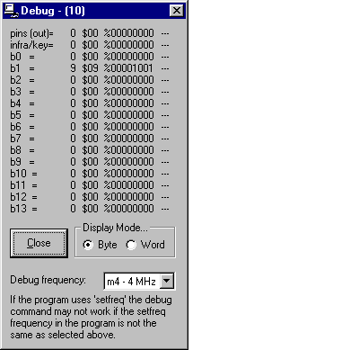
for b1 = 0 to 255
debug b1
next b1
goto start:
Press the F4 function key to check your syntax. Correct any errors in the program.
Press the F5 function key to download the program to the Picaxe.
You should see a download screen and a progress indicator as the program loads. Once it is done a Debug windows will come up and show the value of B1 (a variable in the Picaxe) changing from 0 to 255 over and over.


‘led test program
start:
high 7:low 6
if pin6 =1 then reed:
pause 300
low 7:high 6
if pin6 =1 then reed:
pause 300
goto start:
reed:
high 6
high 7
pause 5000
goto start:
The two LEDs should blink on / off. When a magnet comes close to the reed switch both LEDs should stay on for 5 seconds.
‘pot test program
start:
readadc 0, b1
readadc 1, b2
debug b1, b2
goto start:
If any of the variables do not change make sure that the potentiometer associated with that variable is properly connected to +5 volts on one side and ground on the other. For example, if B2 stays at 255 it is likely that one end of the pot that goes to Picaxe pin 1 is properly connected to +5 volts but the other is not connected (or has a bad solder joint) to ground.
‘motor test program
high 1
low 2
start:
for w1= 200 to 1000 step 40
pwmout 3, 249, w1
pause 400
next w1
pause 5000
for w1= 1000 to 200 step -40
pwmout 3, 249, w1
pause 400
next w1
pause 5000
toggle 1
toggle 2
goto start:
The motor should start slowly, speed up, run for a few seconds, slow, stop, reverse and repeat. If you note a tone coming from the motor that is due to the PWM pulses being used to activate the “H-bridge”
Software – how it works
testLED.bas
a. The first line is a comment (starts with an apostrophe)
b. The second line is a label “start:”that is used as an address that the program can return to when needed.
c. “high 7 and low 6”turn the LED on output pin 7 on and the one on output pin 6 off
d. “if pin6 = 1 then reed:”does a test – if input pin6, which goes to the reed switch, is connected to 5 volts then it jumps to the label “reed”
e. “pause 300”waits for 300/1000 seconds
f. The next three lines switch the LEDS that are lit, check for the button being pushed and pause again.
g. “goto start:”starts over
h. “reed:”is another label – the program goes here when the switch is on. The lines that follow turn both LEDs on, pause for 5 seconds and return to “start:”
testMOTOR.bas
a. The first two program lines, high 1 and low 2, set the LM293D motor control chip to turn in one direction. If both were high or both low the motor would not run
b. After the “start:”label is a for/next loop. It tells the computer to count from 200 to 1000 by 40’s and to store the current number in a storage place, or variable, called W1
c. The magic happens in the next line, “pwmout 3, 249, w1”- this line tells the computer to send a variable voltage to the enable pin on the LM293D. You may recall that the enable pin on this device turns it on and off. It interprets 5 volts as on and 0 volts as off. The pwmout command sends a series of pulses that can simulate voltages between 0 and 5 volts. The higher the voltage it sends with this command the faster the motor spins.
d. After the pulse is sent the program pauses for 400/1000 seconds
e. “next w1”tells the program to continue counting with the for/next command.
f. Once the computer counts up to 1000 it pauses for 5 seconds and counts back down with the “for w1 = 1000 to 200 step -40”command.
g. After another 5 second pause the direction pins are toggled, that is the one that is on goes off and the one off goes on and the program continues
testPOT.bas
a. This simple program uses the command “readadc”to read a voltage between 0 and 5 volts on a pin and report that voltage as a number between 0 and 255.
b. “readadc 1, b0”reads the voltage on pin 1 and places the result in the variable b0 – the second readads reads pin 2 into b1
c. “debug b0, b1”has the program report the value of the variables to a box on the programming screen . This is an easy way to see what is happening with a program.
Auto reverse
software
The objectives of this program are
Since this is the main program that is used for the engine controller it is much more detailed containing comments on most lines and using word labels to represent variables. This makes the program much more understandable. The “symbol”command that is used more than a dozen times at the top of the program substitutes a word for a pin or variable. Besides making a program more understandable, it also allows you to easily modify a number that occurs at a number of places in a program by simply changing its value in the symbol area.
The rather cryptic command “setint i_rupt, i_rupt” sets up a very powerful capability of the program called an interrupt. The interrupt forces the microprocessor to continually look at one or more of the input pins and to immediately react if the condition that is being looked for is met. The command “setint i_rput, i_rupt” (i_rupt =%01000000) tells the computer to look at input pin 6 and to go to the interrupt part of the program if that pin becomes high. This happens when the reed switch is closed by a magnet on the track.
The section of the program after the label “interrupt” is executed whenever the engine passes over a magnet.
The other special feature of the program is the variable “magnetFlag” that has the microprocessor skip over the magnet that told it to reverse. If this is not used the engine will go back and forth over the same magnet over and over again! This was discovered the first time I ran the prototype on a track with a magnet. The engine passed the magnet, slowed, paused and reversed and promptly repeated the sequence as soon as it passed over the magnet again! I had a wonderful oscillating railroad engine! Cute, but not of much use until the “magnetFlag” was added.
'd. bodnar
' third pot added
'speeds up motor and slows / reverses on
reed switch
'magnetFlag (bit0) is flag to skip 2nd pass
over same magnet on reverse
symbol
ver
= 9
'version to flash at start
'symbol
howlong =
100
'delay in accelerate / decelerate loops
symbol
HBridgeD1 =
1
'output - H-Bridge chip direction pin
symbol
HBridgeD2 =
2
'output - other H-Bridge chip direction pin
symbol
pulse
= 3
'output - H-Bridge pin for pwm
symbol
LED
= 6
'output - LED on pin 6
symbol
LED2
= 7
'output - LED on pin 7
symbol
magnetFlag =
bit0
'used to skip over first magnet on reverse
symbol
doitflag =
bit3
'set if ready to reverse
symbol
tone
= b1
symbol
flashLED =
b2
'variable for for/next flash
symbol
stoptime =
b3
' long to pause
symbol
toppot
= b4
'read pot for top speed
symbol
stoppot
= b5
'read pot for pause time
symbol
accloop
= w3
'variable for accelerate for/next
symbol
top
= w4
'top of accelerate for/next
symbol
period
= 124
'constant for PWM period
symbol
lowend
= 300
'constant for small end of for/next loop
symbol
stp
= 4
'constant for step in for/next loop
symbol
i_rupt
= %01000000
'binary for pin 6 interrupt
symbol
temp
= b10
'temporary variable
symbol
accpot
= b11
'read pot for acceleration /decel rate
'the next three lines flash major version
number on LEDs at startup
high LED:low LED2
for temp=1 to ver:toggle led:toggle
led2:pause 200:toggle led:toggle led2:pause 200:next temp
pause 1000
setint i_rupt, i_rupt
'Use interrupts to check for pin 6 being high
high HBridgeD1:low HBridgeD2:magnetFlag=0
'initialize, forward -clear skip magnet flag
speedup:
gosub get_toppot:
'read setting from top speed potentiometer
for accloop=lowend to top step stp
'accelerate loop start
pwmout
pulse,period, accloop
'send
pwm pulses
toggle led:toggle led2:
'blink LEDs
pause
accpot
'pause sets acceleration rate
toggle
led:toggle led2:
'blink LEDs
pause
accpot
'pause sets acceleration rate
if
doitflag=1 then slow_reverse:
'doitflag set by interrupt detecting magnet
next accloop
'back to start of for/next loop
maintain_speed:
'keep steady speed routine
high
led
'LED on
gosub
get_toppot:
'read setting from top speed potentiometer
pwmout
pulse,period, top
'send
pwm pulses
low
led
'LED
off
if
doitflag=1 then slow_reverse:
'doitflag set by interrupt detecting magnet
pause
50
'brief pause
goto maintain_speed:
'go to start of maintain_speed loop until interrupt
slow_reverse:
'decelerate reverse routine
high LED:low LED2
'toggle LEDs
gosub get_toppot:
'read setting from top speed potentiometer
for accloop=top to lowend step -stp
'decelerate loop start
high
LED2
'turn off LED
pwmout
pulse,period,accloop
'send
pwm pulse
toggle
led:toggle led2:
'provides a pre-scale of 1:4 use $06 for
pause
accpot
'pause
low
LED2
'turn on LED
next accloop
'back to start of acceleration loop
toggle HBridgeD1:toggle HBridgeD2
'reverse direction
magnetFlag=1:high LED
'set magnet flag & light LED
pwmout pulse, period,0
'send pwm for stop!
readadc 1,stoptime
'get pot reading for stop time
for flashLED=1 to stoptime
'pause
flashing LED routine
high
LED
'light LED
temp=stoptime-flashLED
'use temp variable for computation for next step
pause
temp
'wait
low
LED
'off
LED
pause
flashLED
'wait
next flashLED
'back to start of flash for/next loop
doitflag=0
'reinitialize flag
goto speedup:
'start over again!
interrupt:
'jumps here if magnet detected
if
magnetFlag=0 then doit:
'if no flag do decelerate & reverse
if
magnetFlag=1 then makemagnetFlag_0:
'if flag was set reset it (hit magnet on way back)
doit:
'label of place to jump to
doitflag=1:low
LED2
'set flag to reverse
goto
back1:
'skip over next part
makemagnetFlag_0:
'clear flag routine
high
LED2:low LED
'light LED
magnetFlag=0
'clear flag
pause
800
'wait 8/10 sec to make sure we don't detect same magnet again
doitflag=0
'clear flag
back1:
'label of place to jump to
setint
i_rupt, i_rupt
'reset interrupt for next magnet detection
return
'back to where we were when magnet detected
get_toppot:
'start of read pot subroutine
readadc
2,toppot
'get pot value
top=toppot
* 4
'scale
to max of 1023
readadc
0, accpot
'get accelerate / decelerate pot
return
'return to place were gosub was called and continue
Installation
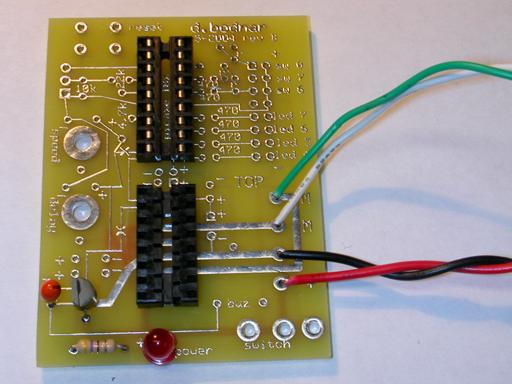
Before installing the board you need a direct connection to the engine’s motor. Locate these two wires and disconnect them from the other wiring within the engine. Connect them to the two contacts on the board labeled “M”. If you plan on using track power for other trains at the same time as the battery operated engine make sure you have disconnected any track power pickups in the engine.
Connect your battery pack to the power connections on the board through a fuse or circuit breaker and an on/off switch.
The reed switch should be glued to the bottom of the engine so that it will pass within a distance of ¼” or less of the track mounted magnet (remember that magnetic field strength decreases rapidly as the distance increases.) I have found that placing the reed switch inside a channel in a piece of wood protects its glass package and gives a larger gluing surface. When gluing the reed switch make sure that the flat sides of the reeds are down as this is the best position for detecting a magnetic field.
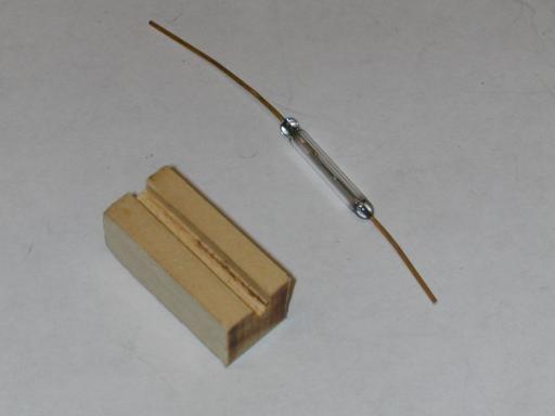
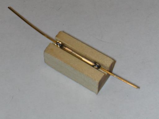
If you need to bend the leads on the reed switch, as I have in the prototype, make sure you grip the wire coming from the glass with a pair of pliers and bend the wire beyond the pliers. If you try to bend the wire by holding the glass in your hand you are sure to break the glass of the reed switch.
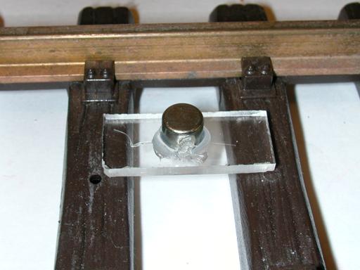
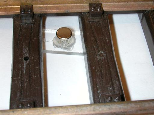
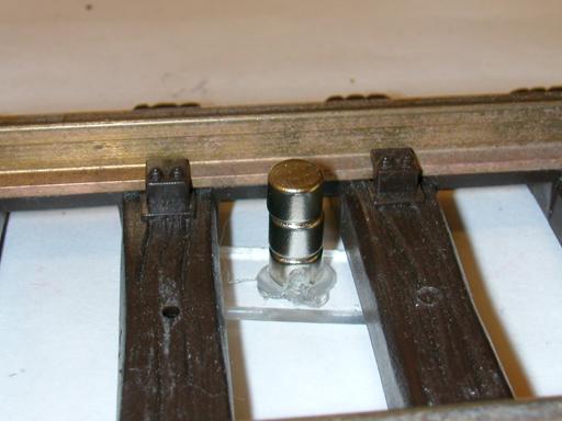
Magnet Placement
I placed magnets by gluing one small cylindrical magnet to
a piece of Plexiglas that is just long enough to be held down by adjoining ties.
I put the Plexiglas under the track and add additional ¼” magnets to
make a stack that comes within ¼” of the reed switch.
This arrangement works well!

Troubleshooting
1.
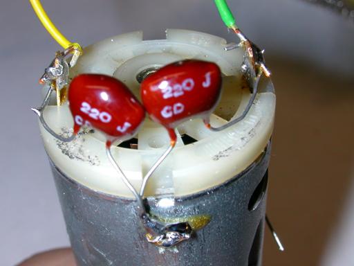
Killing electrical noise from motors
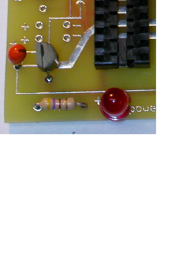
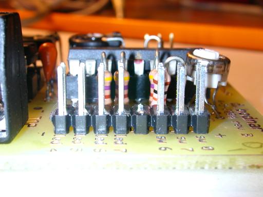
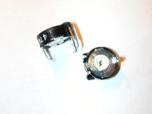
Since we are using a single power supply (one set of batteries) to power both the motor and the microprocessor it is possible that some electrical interference, generated by sparks within the motor, will get back to the microprocessor. Capacitors are the best way to filter out this noise. The 10 mfd tantalum capacitors that I have used have been sufficient to suppress noise in the 3 engines I have tested. If you find your system operating intermittently or randomly resetting you may need to add more suppression. Adding 220 pf capacitors between each terminal on the motor and its case can help a great deal. (see the photo)
2.
Setting PWMOUT variables for different motors
The PWMOUT command uses two arguments, period and duty cycle. In the programs I have used 124 as the value for the period and changed the duty cycle with the variable in the for/next loop. You may need to experiment a bit with the period value to suit your engine’s motor. To simplify this process you can try this program. It changes the period and duty cycle based on the position of the speed and delay pots and uses the debug window to display their values. Just adjust the two pots to get a good speed range and smooth running motor. Once you find a value for “period”, b2, that you like change the “symbol period” setting in the program accordingly.
'MOTOR
test #2 d. bodnar
'used
to adjust period and duty cycles to minimize "noise" coming from motor
'124
works well as period
symbol
L293D1
= 1
'output - L293D direction pin
symbol
L293D2 = 2
'output - other L293D direction pin
symbol
pulse =
3
'output - pin for pwm
symbol
toppot = b0
'read pot for top speed
symbol
period
= b2
'variable for period from adc
symbol
duty_cycles =
w3
'top of accelerate for/next
symbol
temporary =
w4
high
l293d1:low l293d2
'spin in one direction
start:
gosub
get_toppot:
'read setting from top speed potentiometer
pwmout
pulse,period, duty_cycles
'send pwm pulses
goto
start:
get_toppot:
readadc
2,toppot
'get pot value for max speed
duty_cycles=toppot*4
'scale to max of 1023
readadc
1, period
'get period value from pot
temporary=period*4
if
duty_cycles > temporary then fixit:
debug
toppot
'show value in debug window
debug
period
'show value in debug window
debug
duty_cycles
debug
b2
return
fixit:
duty_cycles=period*4
return
Ideas for
Enhancements
Below are some ideas for enhancements to the system. The Picaxe is capable of much more than just reversing an engine. Let me know if any of these ideas are of interest to you or pass along ideas of your own. They are all possible with minor modifications to the hardware and/or software.
Now for your ideas!
I hope that this project gives you enough information to
consider building your own, custom train control system.
The “store bought” units are great but there is something about doing
it yourself! Good luck and let me
know if I can help.